An AI 3D model generator can turn a product image into a three-dimensional starting point quickly, but a plausible shape is not the same as a manufacturing definition. A photograph contains visible form, color and proportion. Manufacturing also requires scale, hidden geometry, interfaces, wall conditions, material assumptions and inspection requirements. The practical workflow therefore has two distinct jobs: reconstruct the product intent from incomplete visual evidence, then validate the reconstructed model against a selected production process.
What an AI 3D Model Generator Can Infer From an Image
Visible Surfaces Provide Form, Proportion and Style Cues
A clear image gives an AI 3D model generator useful evidence about silhouette, major surfaces, visible openings and the relationship between prominent features. Multiple images taken from controlled angles provide a stronger basis than one dramatic view because reviewers can compare the same feature across orientations.
The generated form can help a team discuss appearance, compare proportions and identify information gaps. However, pixels do not establish an exact diameter, wall thickness or assembly clearance. Even a polished render may preserve perspective distortion from the source image. Reviewers should label visually inferred features separately from measured or specified features.
Hidden Geometry, Scale and Interfaces Must Be Supplied or Reconstructed
A single view leaves the rear surface, internal cavities and occluded connections unknown. An AI 3D model generator may fill those gaps with statistically plausible geometry, but plausibility cannot establish design intent. Without a known reference dimension, several differently sized models may match the image equally well.
Before engineering work begins, the team should list every unresolved element: overall dimensions, mating surfaces, fastening points, openings, part boundaries and functional clearances. Intended use, expected loads, material direction and production quantity also affect structural decisions. This uncertainty register prevents generated details from being mistaken for approved requirements.
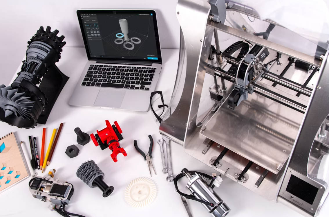
From Image-to-3D Output to Editable CAD
Build a Reference Pack Before Generating Geometry
A useful reference pack combines front, side, rear and detail views with at least one reliable scale reference. A marked sketch can identify critical dimensions, fixed interfaces and surfaces that must retain the visual design. The brief should also state the product function, likely material, assembly relationship and purpose of the first physical sample.
Inputs should distinguish facts from preferences. A connector location may be fixed, while a corner radius may remain open for refinement. Unknown information should stay explicitly unknown until a designer, engineer or buyer resolves the question. Better input does not remove the need for review, but the reference pack makes each revision more deliberate.
Rebuild Critical Features as Parametric CAD
Image-to-3D systems commonly produce mesh geometry that is useful for visualization. Mechanical development usually needs stable faces, selectable edges, meaningful holes and editable dimensions. For that reason, the generated output often serves as a shape reference rather than the final engineering file.
Critical geometry should be rebuilt or defined in CAD around datums, sketches, constraints and features. A hole should have a diameter, axis and depth; a mounting face should have a controlled location; a pattern should respond predictably when one driving dimension changes. Parametric CAD reconstruction restores engineering intent that a triangle surface cannot carry. The AI 3D model generator accelerates the initial interpretation, while the feature structure supports controlled revisions.
Manufacturing-Ready 3D Model Validation Gates
Verify Dimensions, Interfaces, Walls and Closed Geometry
The first validation gate checks whether the model is internally coherent. Reviewers confirm units, overall dimensions, critical interfaces, part boundaries and reference datums. Closed solids should not contain gaps, unintended intersections or duplicated surfaces. Thin regions and abrupt transitions require attention because appearance alone does not demonstrate structural suitability.
Assembly questions belong in the same gate. Mating parts need defined contact surfaces, fastener access and realistic clearance. Any tolerance must relate to function and the selected process rather than being copied across every dimension. A manufacturing-ready 3D model is therefore an evidence-backed package, not simply the cleanest-looking output from an AI 3D model generator.
Apply Process-Specific DFM for Printing, CNC or Molding
Manufacturability changes with the production route. A 3D-printed prototype raises questions about orientation, supports, accessible finishing areas and material behavior. CNC machining requires a review of tool access, setups, internal corners and the amount of material removed. Injection molding introduces parting, draft, wall transitions, ejection and tooling considerations.
One generic manufacturability score cannot approve all three routes. The team should select a likely process, review the model against that process and record open risks. If quantity, material or functional requirements change, the review may also need to change. This gate turns an attractive digital result into a model that a supplier can assess responsibly.
Prototype and Iterate Before Production Release
Turn Prototype Findings Into Controlled CAD Revisions
A prototype should answer named questions. Appearance samples can test proportion and handling. Fit samples can check interfaces and assembly sequence. Functional prototypes may explore support features or material choices within an agreed test plan. Observations should be recorded as pass, revise or unresolved rather than discussed only in an informal review.
The corresponding CAD revision should identify what changed and why. This discipline keeps the AI 3D model generator within a traceable product-development process. The approved file remains connected to test evidence, while rejected geometry does not quietly return in a later version.
Choose a Prototype Route That Tests the Highest-Risk Assumption
A visual shell may be sufficient for an appearance decision, while a machined sample may be more appropriate when material, interfaces or fastening behavior matter. A molding-related feasibility review becomes relevant when repeat production and tooling geometry drive the decision.
Teams should prioritize the uncertainty with the greatest downstream consequence. Geometry, material, quantity and required evidence determine the route. After testing, the team can refine the CAD model, repeat a focused check or approve the next manufacturing stage.
How Momaking Connects Images, Structural Design and Manufacturing
From a Reference Image to a Reviewable Structure
Momaking supports structural-design work that can begin with a customer image or design concept. The verified workflow combines image processing, 3D modeling, structural analysis, visual feedback and customer participation. This approach helps turn incomplete visual intent into a reviewable structure while keeping dimensions, interfaces and open engineering questions visible.
We can use the reference pack and customer feedback to refine the structural direction. The service does not make every generated surface automatically production-ready. Human review remains necessary before the approved design enters a physical process.
Match the Reviewed Model to 3D Printing, CNC or Molding
Momaking provides 3D printing, CNC machining, mold manufacturing and injection molding services. A reviewed model can be matched to one of these categories according to geometry, material, quantity and validation goals. The buyer should also provide finish, inspection and assembly requirements so the manufacturing discussion reflects the intended part.
This workflow supports the handoff from structural files to a prototype or production conversation. Final feasibility, tolerances and process details remain project-specific and should be confirmed before release.
FAQ
Q: Can an AI 3D Model Generator Reconstruct a Complete Product From One Image?
A: Not reliably. One image can communicate visible form, but hidden surfaces, exact scale, internal structure and interfaces remain underconstrained. Additional views, dimensions and requirements are needed.
Q: Can the Generated Model Go Directly to Printing or CNC?
A: Usually not. The model first needs geometry, dimension, interface and process-specific checks. Critical features may need reconstruction as editable CAD before a supplier can manufacture or inspect the part.
Q: What Should a Buyer Send Momaking With the Reference Image?
A: Provide additional views or sketches, known dimensions, intended function, fixed interfaces, material expectations, quantity and the decision that the first prototype must support. Clear inputs make structural review and process selection more actionable.